Electrical Assembly

Ready to start?

Tips

IMPORTANT:


1. Power Motor Controller from Raft Board

Materials

Procedure:

  1. Check that PICO is OFF, unplug from computer if needed
  2. Attach the black wire from the ground on the raft board to the ground on the motor controller (middle one)
  3. Attach the red wire from the +V output of the raft to the +12V input to the motor controller (the outer one)

Note:
Loosen screw terminal first, then put wire in all the way, then tighten. Tug gently to make sure it's secure.

ground wire from raft to motor controller
GND wire first
power wire for hbridge to raft
Motor Power wire

2. Attach Battery Holder

Materials

Procedure

  1. Move power and ground wires to the side so that they are not crushed by the battery holder
  2. Tighten fasteners
  3. Put battery into holder
exploded view of battery attachment
Use same procedure as other mechanical assembly steps
battery plugged in
Side of battery with cord sticks out

3. Plug in Servo Motor

Steps:

  1. Make sure board is off
  2. Activate level shifter with shunt on pin 18
  3. Connect orange wire into PWM *18
  4. Connect red wire into +5V
  5. Connect brown wire into GND

4. Make Servo Face Forwards

Materials

Steps:

  1. Plug in Pico to raft (ask if you need help)
  2. Plug in battery to raft
  3. Turn on board (use POWER switch)
  4. Put pico into BOOT mode: hold BOOT, press RESET, release BOOT
  5. Go here for a reminder on how to upload code to your pico
  6. within rcc-pico/dev/pico/using-robot-examples, find servo.cpp
  7. Add to CMakeLists.txt, upload to your pico
  8. This code writes the servo to the forward position so the lidar will face forwards

5. Attaching Lidar to Servo

Materials

Steps:

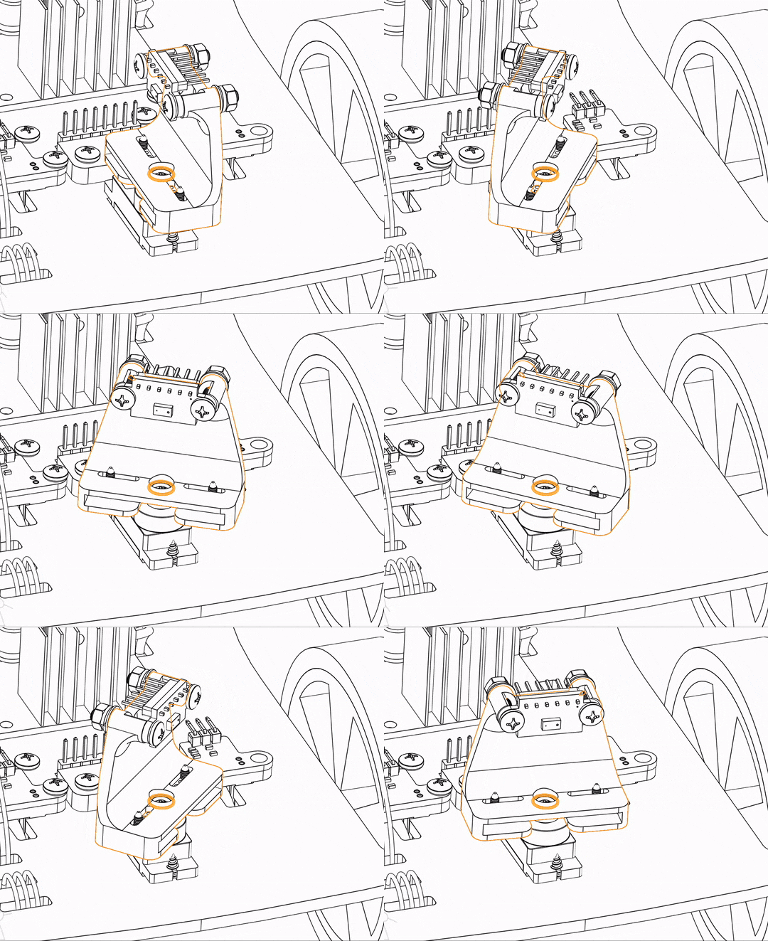
  1. While servo is facing forwards, attach sensor bracket
  2. Fasten Lidar to bracket
exploded view of lidar bracket mount
Attach sensor bracket facing forwards
exploded view of lidar mount
Pins are up

6. Testing Potentiometer with Servo

Steps:

  1. Use shunt to connect potentiometer on GPIO pin 28
  2. Compile and upload servowithpot.cpp
  3. Twist your potentiometer to see full range of servo's motion
  4. If you notice that your lidar's range is uneven, the lidar bracket may have been added to the servo when it was not facing forwards, return to Step 4
gif of servo motion
Should see something like this

7. Plug in Lidar

Steps:

  1. Attach shunts to activate *I2C1 bus, need BOTH pins 14 and 15
  2. Plug Vin to 3V3
  3. Plug GND to GND
  4. Plug SCL to *SCL
  5. Plug SDA to *SDA
    • wire colors do not matter here
    • the other two pins on the lidar are unconnected
  6. Compile and upload lidar.cpp
  7. Prints out millimeters in distance

8. Plug in IMU

Similar to the Lidar, use the *I2C1 bus:

  1. Plug VCC to 3V3
  2. Plug GND to GND
  3. Plug SCL to *SCL
  4. Plug SDA to *SDA
    • wire colors do not matter here, just keep track of your wiring
    • the other four pins on the imu are unconnected
  5. Compile and upload imu.cpp
  6. gently shake/spin robot to test x-axis acceleration, y-axis acceleration, and z-axis rotational velocity

9. Plug in Motors and Test Polarity

Steps:

  1. Make sure battery is unplugged and both leds are off
  2. Screw in red and black wires from motors into motor controller OUT terminals
    • Either polarity works, you can reverse it if needed
  3. Plug in all 6 control wires:
    • ENA to GPIO 7
    • IN1 to GPIO 8
    • IN2 to GPIO 9
    • IN3 to GPIO 10
    • IN4 to GPIO 11
    • ENB to GPIO 12
  4. Compile and upload motors.cpp
  5. Make sure MTRPWR switch is on, should see led on motor controller board
  6. If either wheel is spinning backwards, need to reverse the polarity:
    1. Unplug power!!
    2. Switch the red and black wires on the motor controller for the motor that spun backwards
  7. Turn pico on, now both wheels should spin forwards
  8. For a bonus challenge, modify servowithpot.cpp to control motor power with the potentiometer

10. Plug in Encoders

Steps:

  1. For the Right Encoder:
    • OUT to GPIO 13
    • VCC to 3V3
    • GND to GND
  2. For the Left Encoder:
    • OUT to GPIO 21 (green pin)
    • VCC to 3V3
    • GND to GND
  3. Compile and upload odom.cpp
  4. Spin each of the wheels and you should see the count increase and the led on the sensor blink

Congrats! You're Fully Assembled and Ready to Play!

robot fully Assembled
Fully assembled robot with a v0.3 raft